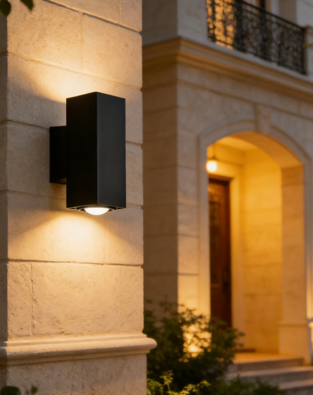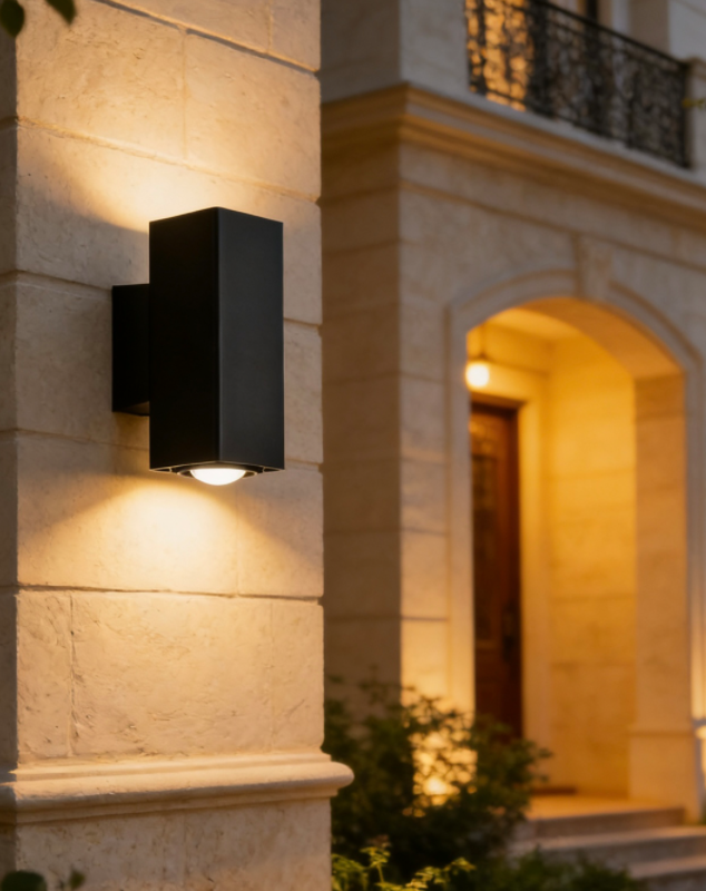
Adding a motion trigger to an existing wall fixture can reduce unnecessary operating time, but the retrofit starts with compatibility rather than a quick wiring change. The circuit, driver, enclosure, and sensor behavior all affect the result. This guide explains a documented approach for property owners, contractors, and importers planning outdoor wall lights motion sensor upgrades.
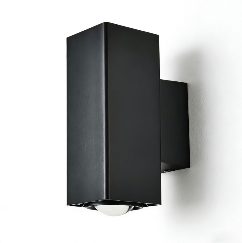
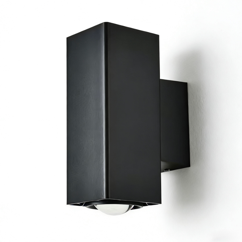
A0696 is a premium wall sconce featuring motion activation, soft glow, and a tempered glass cover. Our product specification includes die-casting aluminum housing, a CREE COB 2x5W LED chip, KEDA driver, 85–265V AC at 50/60Hz input, IP65 outdoor-light rating, dimensions of Ø65 × W100 × H160 mm, and a three-year warranty. While specific retrofit wiring diagram, sensor technology, detection range, and timing settings vary by project, we recommend confirming these details with our team
Audit the Existing Light and Circuit
Record the current fixture model, supply arrangement, switching method, cable route, and mounting condition. Note whether the light is controlled by a wall switch, timer, building system, or shared circuit. Sensor operation depends on the existing electrical design, so a qualified electrician should inspect the installation before any modification.
We recommend checking the housing for cracks, loose covers, water traces, or impact damage before any retrofit. While our A0696 features an IP65 rating as part of its product specification, we advise that an older or altered fitting may not retain the same protection. If the enclosure or cable entry is compromised, we suggest repair or replacement may be more suitable than adding a sensor.
Choose an Integration Route
There are two common project paths. An external sensor can control the existing light through an approved switching device, or the fixture can be replaced with a model that includes motion activation. The route depends on load compatibility, available space, local code, and the property’s control sequence.
At Keyida,A0696 is a motion-sensor wall sconce, so it can be evaluated as a replacement reference rather than proof that every existing lamp accepts a sensor. Compare the wall opening, fixing points, cable route, and visual output. The listed size of Ø65 × W100 × H160 mm should be checked against the proposed mounting detail.
Plan Sensor Coverage and Light Direction
Map the approach area before fixing the sensor. A side door, driveway, and pathway create different movement patterns. Aim the sensing field toward the route while aiming the light toward the landing, wall, or steps. The two directions may not be identical, especially where guests approach from an angle.
Test the proposed position with temporary marks. Walk at normal speed, carry a service cart, and check movement from both sides. Note windows, reflective paving, branches, and signs that could produce unwanted triggers or block the field. Do not add a detection range or delay to the specification unless the supplier provides it.
A soft glow can help an entrance feel welcoming, while a harsh beam may cause discomfort when it activates near eye level. Observe the scene from indoors and outdoors. If the result is unsuitable, adjust physical placement or shielding before changing the control plan.
Install Through Qualified Electrical Work
Switch off the circuit at the appropriate disconnect and verify isolation. A licensed electrician should connect the sensor, switching device, and light according to approved diagrams. Protect joins from moisture and impact, keep them accessible for inspection, and label the circuit in the distribution record.
Avoid drilling extra holes in the A0696 housing or adding unapproved sealants. The product table identifies die-casting aluminum with tempered glass and an IP65 outdoor-light rating. Preserving those documented features requires careful mounting and reassembly. Any external sensor enclosure should also follow its own installation instructions and environmental requirements.
If the project retains an older fixture, confirm that its driver and switching method work with the selected sensor. Flicker, delayed startup, or failure to turn off can indicate a mismatch. Capture measurements and observations for the electrician and supplier instead of assuming the sensor is at fault.
Commission Day, Night, and Override Behavior
After the wiring is checked, test activation in daylight and darkness. Walk through the zone from each expected approach, then leave the area and observe shutoff behavior. Record manual override, repeated movement, and recovery after a power interruption.
Photograph the final sensor angle, fixture position, and cable route. Record the model, finish, control device, test date, and any pending action. This file helps maintenance teams reproduce the approved setup when plants grow or a wall fixture is replaced.
Prepare a B2B Retrofit Package
For distributors, importers, and contractors, combine the approved drawing with the A0696 material, LED-chip, driver, input, IP65, size, and warranty information. Request current sensor documents and samples before confirming an OEM or ODM batch.
Our A0696 includes a three-year warranty for product support.We recommend clarifying how warranty and service arrangements apply when an external sensor or third-party control is added. We suggest keeping the original fixture specification separate from retrofit components, responsibilities, and local compliance records for clear documentation.
Adding a motion sensor is a coordinated design task: audit the circuit, select a compatible route, align detection with illumination, install through qualified work, and test real movement. At Keyida, we support project, wholesale, OEM, and ODM customers with documented product information for LED building facade lighting and other outdoor applications.